According to the National Pork Producers Council (NPPC), the United States has more than 60,000 pork producers that annually market more than 115 million hogs, leading to an average total gross income of more than US$20 Billion1 . Supporting this industry requires an estimated water demand of 525,000,000,000 gallons/yr (1,990,000,000 m3 /yr) according to a 2011 report by the Pork Checkoff organization2 . The water uses in the pork production life-cycle are diverse and shown in figure 1.
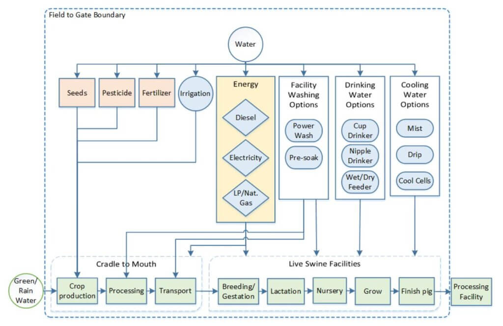
A majority of the freshwater use (67%) is dedicated to growing food crops for the animals, with the remaining demand used for service water that is farm/facilities related (24%), animal drinking water (8%), and feed mixing water (1%). Opportunities exist within the entire pork production pipeline to capture, treat and reuse water. Here we focus on the opportunity to reuse the 24% of water demand associated with facility washing, animal cooling water and energy-related water cooling.
According to the 2011 Pork Checkoff report2, 32% of the hog production facilities use anaerobic lagoon systems for manure management, whereby manure and wastewater is captured in a subfloor system and directed to an adjacent lagoon for collection. Anaerobic lagoons are deep earthen basins with sufficient volume to allow solids to settle so that they can be naturally anaerobically digested3.
However, wastewater from typical anaerobic lagoons cannot be discharged directly to receiving water bodies and must be followed with an aerobic or facultative lagoon to provide another level of treatment before discharge. The main disadvantage to this method of treatment is the required acreage (0.5 to 2 acres)3 and retention time. A given wastewater batch must stay in the anaerobic lagoon between 1 and 50 days depending on the temperature of the wastewater3.
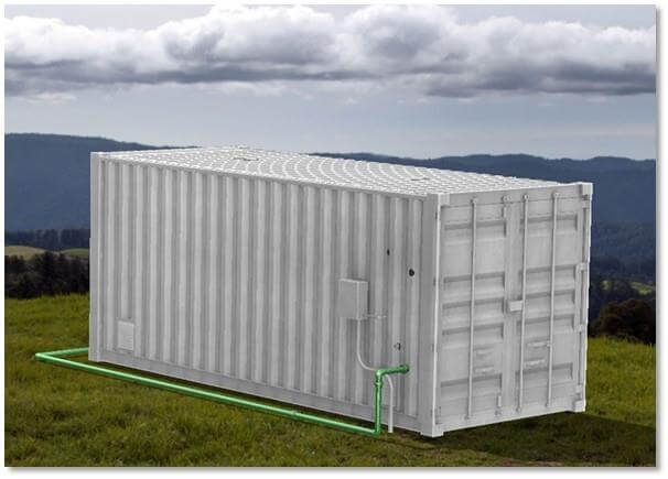
The Aquacycl BETT™-line of products can help to reduce the overall land footprint and treatment time of hog production wastewater by providing up to 20,000 gallons per day (76 m3/day) of treatment in a 40ft x 8ft (12m x 2.4m) land requirement (dependent on waste stream). Smaller units are also available (Figure 2) based on the end-user requirements and waste stream. Multiple units can be networked for larger wastewater volume demands. Each BETT™ unit can provide:
- Energy recovery as direct electricity (no methane), in the range of 0.2 to 0.8 kWh/kg-COD treated
- Fast treatment times, up to 4-hour hydraulic residence times
- Sludge elimination, up to 80% total suspended solids removal by rapid microbial degradation of solid and soluble carbon
- Onsite water reuse enabled by optional tertiary treatment technologies
Case Study – Small-scale agriculture center
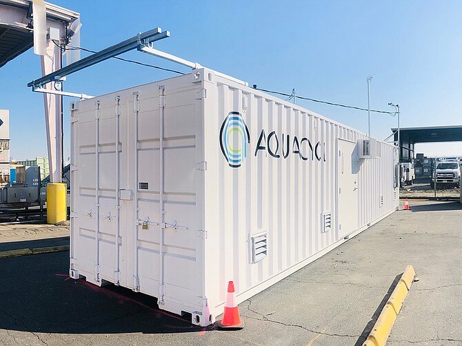
The Aquacycl team installed and operated a small-scale demonstration of the BETT™ systems at a teaching farm located at San Pasqual High School, in Escondido CA USA (Figure 3).
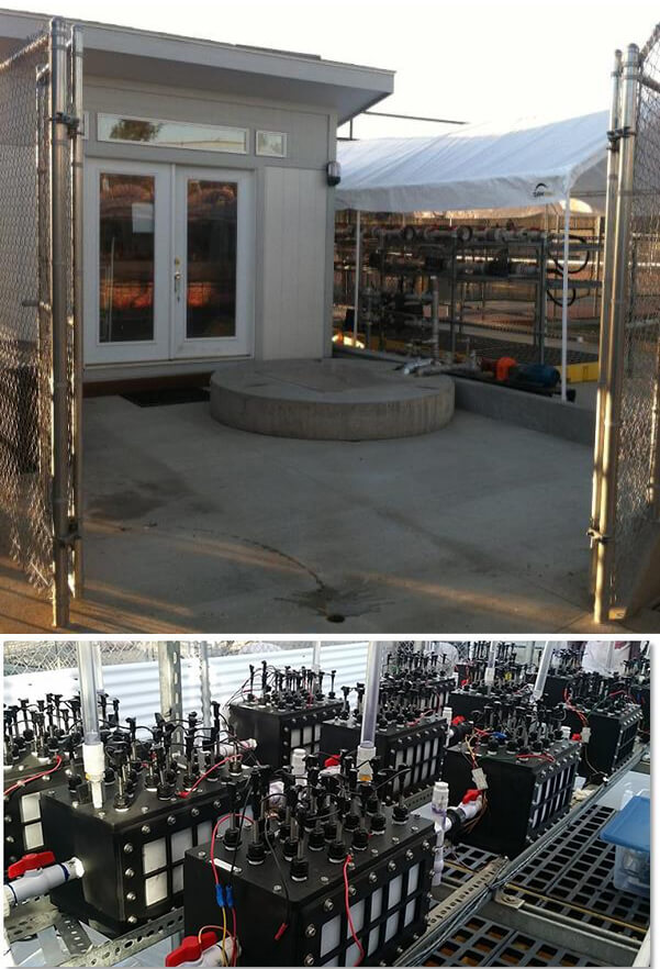
The purpose of this BETT™ system installation was to demonstrate the technology in an agriculture setting and engage students at the high school with hands-on learning about farm water management.
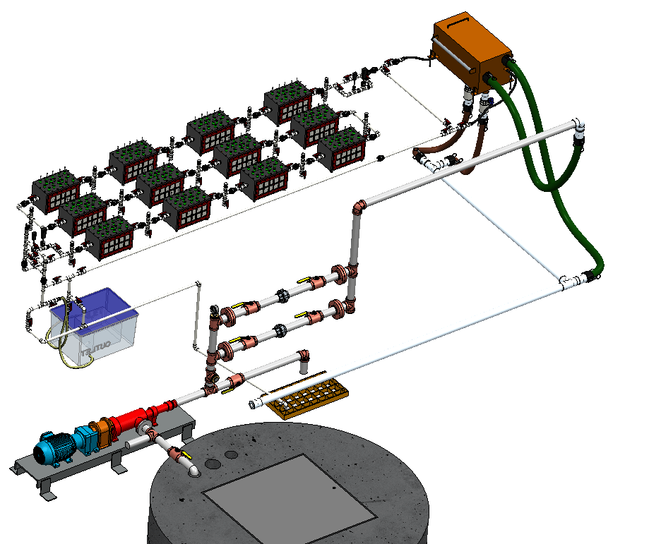
The system was constructed using funds from the Roddenberry Foundation and included a concrete pad with drainage, a 1,500 gallon (5.7 m3) underground sump pit, a cavitation pump, a peristaltic pump, feeder box, and twelve BETT™ reactors operating in hydraulic series with a total volume of 29 gallons (0.1 m3). A schematic of the system is shown in Figure 4. The treated effluents from the BETT™ system were disposed to sanitary sewer.
The system has been running continuously since March 2016. Here we present a summary of the first 200 days of operation.
Results
The system was first operated in a batch mode for 38 days to establish the microbial communities and electrochemical performance. After day 38, the system was operated in continuous mode with a hydraulic retention time of 4-hours through the system and flow rate of 0.1 gpm (0.38 lpm). Inflow and outflow samples were collected to analyze the chemical oxygen demand (COD), nitrate, nitrite, ammonium, sulfate, pH, dissolved oxygen (DO), and total suspended solids (TSS) from the system. In addition, energy recovery was evaluated by measuring the current, voltage and power from each of the twelve reactors.
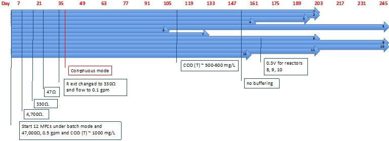
Some operational changes were made during the operation of the system to accommodate analyses, and/or farm constrains (e.g. no hogs onsite). The schedule shown in Figure 5 outlines all the operational changes that occurred over the first 250 days of operation.
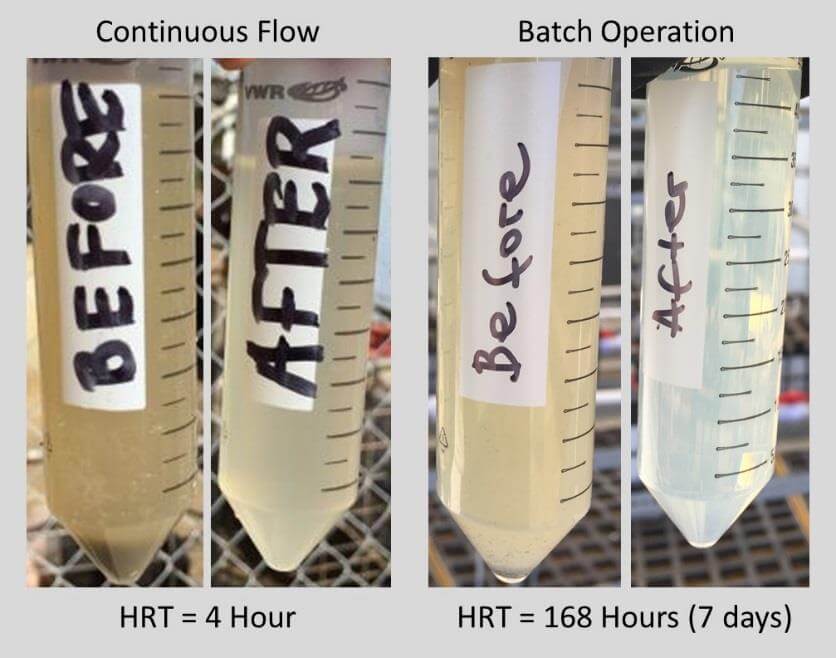
After 200 days of operation, the system was reset to batch-mode with a 7-day residence time. The Total COD in the wastewater was also reduced to approximately 500 mg/L during this period due to the fewer pigs at the farm. Figure 6 shows pictures of before and after treatment from the 4-hour retention time (continuous mode, starting COD of 1000 mg/L) and 7-day retention time (batch-mode, starting COD of 500 mg/L).
pH and Dissolved Oxygen
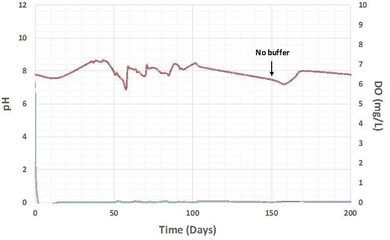
The measured pH and DO of the system are shown in Figure 7. The pH of the BETT™ system was initially buffered with 33mM carbonate. However, buffering agents were no longer added after day 150. The pH dropped from 7.8 to 7.6 when the addition of buffer stopped; however, the pH returned to a relatively stable reading of 8.0 within 20 days. The DO of the system remained near zero, which is consistent with anoxic operation and anaerobic metabolism.
Chemical oxygen demand
Figures 7 shows the data sets for COD inflow, outflow and removal over time; and Figure 8 shows COD removal rate over time. It is apparent that the COD removal is dependent on the COD inflow. It should be noted that on day 102, the inflow COD dropped to between 500 mg-COD/l and 600 mg- COD/l because fewer pigs were at the farm.
The average COD removal rate over the 200-day operational period was 1.6 kg-COD.m-3.day (1.6 g- COD. l-1.d). The best case effluent quality after a 4-hour treatment time was 0.12 g-COD.l-1. The average effluent quality after a 4-hour treatment time was 0.47 g-COD.l-1, which is still within acceptable WHO regulatory limits for water reuse of field crops, industrial crops and forestry (Table 1).
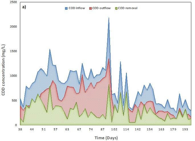
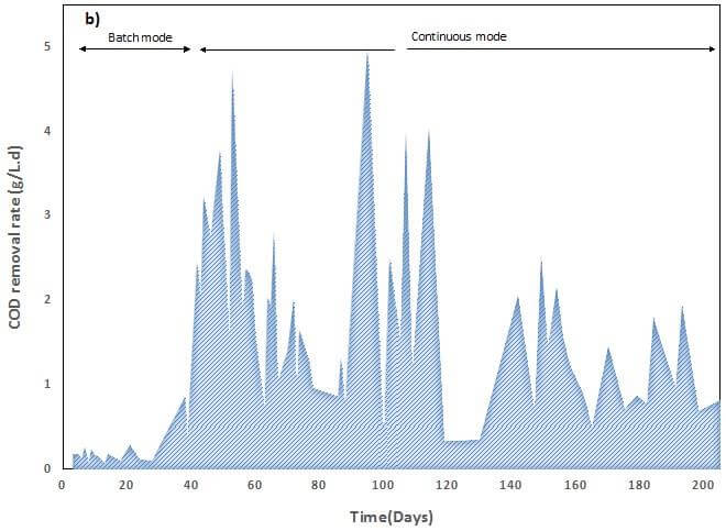
Table 1: BETT™ effluent quality compared to WHO standards for water reuse on field crops, industrial crops and forestry.
| BOD5 (mg/L) | COD (mg/L) | TSS (mg/L) | pH | Nitrate (mg-N/L) | Total N (mg-N/L) | E. coli | Intestinal helminth eggs | ||
| WHO standard | Field crops, industrial crops, and forestry | 300 | 500 | 150 | 6.0- 9.0 | 45 | 70 | NA | ≤1.0 |
| BETT™ effluents | Treated swine wastewater (4hr HRT)† | NA | ≤ 500* | 280‡ | 7.2- 8.1 | < 5⁺ | < 25⁺ | NA | NA |
† average results from continuous flow over 100 days, no post-treatment or disinfection employed
* inflow COD was ~1,000 mg/L (2x higher than typical municipal sewer)
‡ inflow TSS was 1,400 mg/L (5x higher than typical municipal sewer)
* inflow nitrate was 10-29 mg/L and ammonium increased to maximum of 25 mg/L
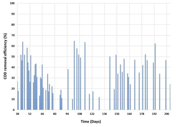
Figure 9 shows the COD removal efficiency over time. The best-case removal efficiency for the 4-hour treatment time was 65%; and the average removal efficiency over the 200-day period, including COD inflow fluctuations was 36%.
Nitrogen
The Nitrogen is a key contaminant in agricultural wastewater and nitrate/nitrite removal is a goal for sustainable wastewater treatment technology. Nitrogen is usually removed from wastewater through biological nitrification and denitrification steps. Nitrification involves the oxidation of ammonium to nitrate with the participation of oxygen and nitrifying bacteria. Nitrate is further reduced to nitrite and ultimately to nitrogen gas. A competing reaction to denitrification is the dissimilatory nitrate reduction to ammonium, which is shown the following scheme:
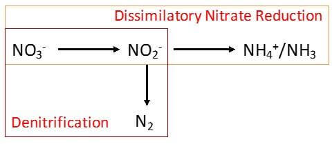
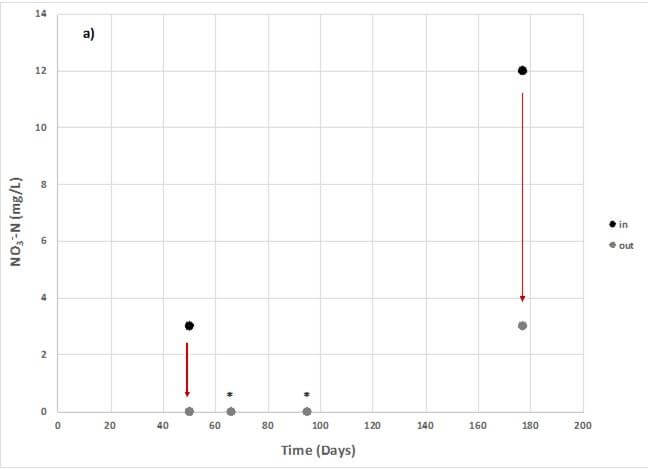
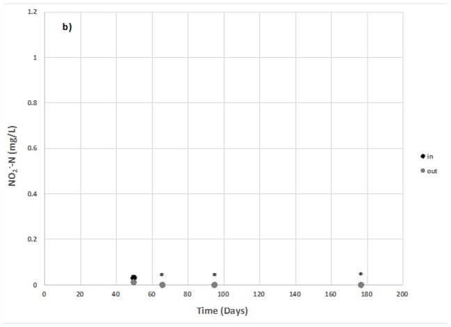
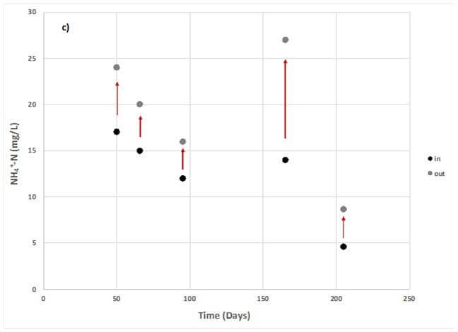
Since the BETT™ systems are operated anaerobically, the dissimilatory nitrate reduction reaction proceeds in the system to convert nitrate (NO3-) and nitrite (NO2-) to ammonium (NH4+). The nitrogen remains as dissolved ammonium since the system effluents are at a neutral pH. Figure 11 shows the nitrate (Figure 11a) and nitrite removal (Figure 11b), and ammonium production (Figure 11c), over the course of operation for a subset of sampling time points during continuous operation, with a 4-hour hydraulic retention time.
Nitrate was consistently removed to below 10 mg/L (as N), which is the WHO and EPA maximum contamination level for nitrate in drinking water. According to Table 1, the BETT™ systems produce effluents that fall well below the WHO nitrate and nitrite limit for water reuse on field and industrial crops.
The measured ammonium increases reached the taste detection limit of ~30 mg/L (as N) in the worst case. However, ammonium dissolved in water can be applied to crop lands and used as a supplemental nitrogen source with standard fertilizer.
Sulfur
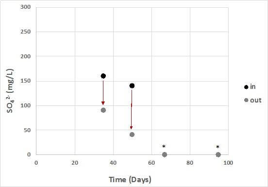
Sulfate is measured a secondary contaminant in water systems and should not exceed 250 mg/L in drinking water, according to US EPA regulations. The BETT™ system reduces sulfate concentrations since it is an anaerobic system. Figure 12 shows the sulfate reduction data. No sulfide was detected.
Energy recovery
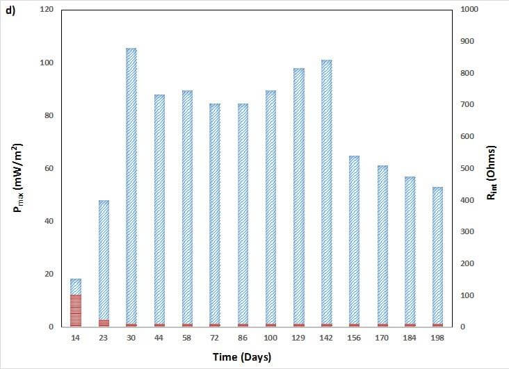
Power production from the BETT™ system was monitored throughout operation. Here we include a summary of power production and total internal resistance from one of the twelve BETT™ reactors (Reactor 5, Figure 13). Each reactor in the treatment train produced equivalent power densities.
Maximum power densities were calculated from cell polarization data that were normalized by the apparent surface area of the cathode (0.1 m2), which is the limiting electrode in the system.
It should be noted that the buffering of the system stopped on day 150, which decreased the conductivity of the reactor solution and resulted in a decrease in overall power density. However, this change did not significantly increase the total internal resistance of the system.
No methane was detected in the outflow solutions or as gas buildup in the reactors. The measured energy recovery as direct electricity was within a range of 0.2 – 0.8 kWh/kg-COD during the time span of operation and varied based on COD loading and operational condition. The energy recovery was measured solely as direct electricity production.
The system was operated with two pumps (totaling 0.3 HP, 5.3 kWh/d) and a data recording device (0.02 kWh). Given that the system removed an average load of 2.6 kg-COD per day, the energy recovery was within a range of 0.5 kWh to 2.1 kWh each day. When the system was running at its highest energy efficiency, then the power generation was supplying half-of the total operational energy demand. It should be noted that power production and energy harvesting was not optimized for the application and minor improvements can lead to significantly higher power outputs using established methods.
Further, the cavitation pump that was initially selected to feed the system was overpowered for the application and the actual pumping requirements for both pumps was found to be less than 0.2 HP (3.6 kWh/d). In the case of actual pumping requirements, the electricity generated from BETT™ can supply at least 58% of the total power when running at maximum energy conversion efficiencies.
BETT™ laboratory results with other waste streams have shown higher energy recovery efficiencies and COD removal rates for less complex wastewaters (e.g. effluents from food & beverage production). These data suggest that BETT™ systems can sustain net-zero energy operations, or energy-positive operations, in the case of high-strength wastewaters (>30,000 mg-COD/L).